Get In Touch
Get In Touch
At present, labor cost is a common problem faced by the manufacturing industry, in the case of not being able to effectively increase the number of workers, it is necessary to find ways to reduce the labor intensity of existing workers, reduce the labor safety risk of employees, and better protect the occupational health of employees. Using the function of the existing plate vulcanizer, the additional equipment parts and devices are transformed, so as to reduce the labor intensity of employees and improve production efficiency.
First, there are problems
in China's rubber conveyor belt production only a few decades of history, among which the vulcanization position is particularly important and special, the conveyor belt vulcanization is mainly the use of plate heating segmented vulcanization method, the degree of automation is generally not high, with high labor intensity, high safety risk coefficient characteristics.
1. High labor intensity. Because every time the plate vulcanizer completes vulcanization (also known as a "pot" in the work), it needs to install another "pot" for the next vulcanization. The purpose is to separate the horn from the vulcanized belt body, pull the vulcanized conveyor belt out of the "pot" by the belt puller, and at the same time pull the unvulcanized belt embryo into the "pot", and then turn the horn again to return to the position to make it close to the belt body that needs vulcanization.
In this process, the operator's body must be close to the 4 "pot" heads, and the horn weighing 35kg~100kg and different thicknesses must be turned back and forth by wrist strength. It has to be repeated dozens of times a day, and the average person's physical strength cannot persist. Conventional vulcanization is up to 18m long, and the horn is longer and heavier. The minimum stroke is 0mm. In the production process, the top iron can be used to drive the horn in and out, that is, the top iron can be connected and fixed with the horn close to the conveyor belt body, so that the horn can be automatically advanced and retreated without manual turning.
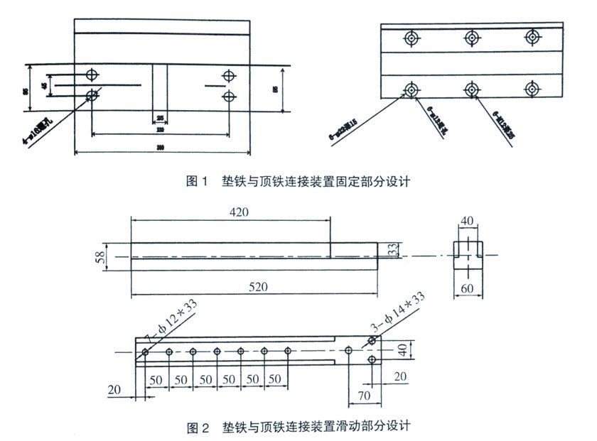
The author designed a connection between the horn and the top iron on the L0000mm×1800mm conveyor belt plate vulcanizer with the fixed installation, see Figure 1 and Figure 2. Wherein, Fig. L is a fixed part, Fig. 2 is a sliding part, and Fig. 2 is assembled on Fig. 1 to form a whole.

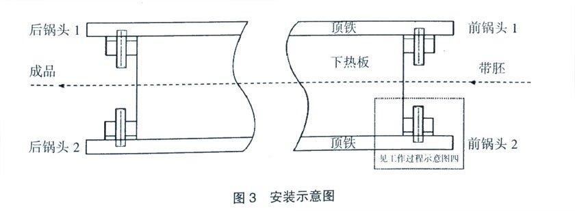
The 4 sets of connection fixing devices that have been made are placed in 4 positions before and after the front "pot" head, and the top and bottom are bolted and fixed. In order to avoid scratches on the belt body at the end of the front "pot" head 2 when the conveyor belt body is pulled out, the upper end of the front "pot" head 2 needs to be parallel to the lower heating plate, and 2~5mm lower than the top surface of the lower heating plate. The installation schematic diagram is shown in Figure 3.

3. Working principle and how to use
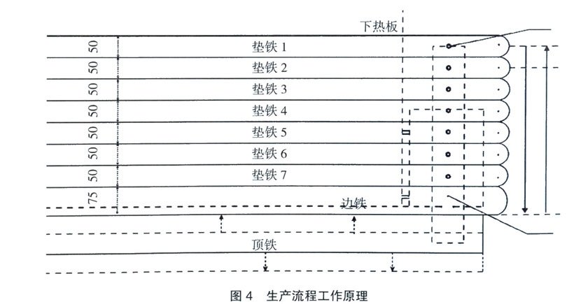
All horn drill L is opened, and the longitudinal center of the horn is divided to both sides, that is, the two horn L are 5068mm in the middle of the horn, and the hole spacing of each horn is 68 + 10000 + 68 = 10136mm; Each horn in the transverse direction is 50mm, the middle position is 25mm, and the drilling hole is φ16~18mm. When the width of the conveyor belt body of the production belt is 1000mm, the horn 1-7 should be fixed; When the width of the conveyer belt produced is 1200mm, the horn 1 and 2 are removed, and the horn 3-7 is fixed; When the width of the production conveyor belt is 1400mm, the horn 1-4 is removed, and the horn is fixed 5~7; When the width of the production conveyor belt is 1600mm, the horn 1-6 is removed, and the horn 7 is fixed. The 4 "pot" heads should complete the above operations at the same time.
Fourth, the effect verification and improvement methods
Through a period of practice, the employees of the rubber conveyor belt flat vulcanizer process can be proficient in operation. In particular, the operators of the 4 "pot" heads no longer use physical operation at all, but only observe and monitor whether the conveyor belt body is stable, in and out in a straight line, and there are no foreign objects, and the transformation has achieved the expected results.

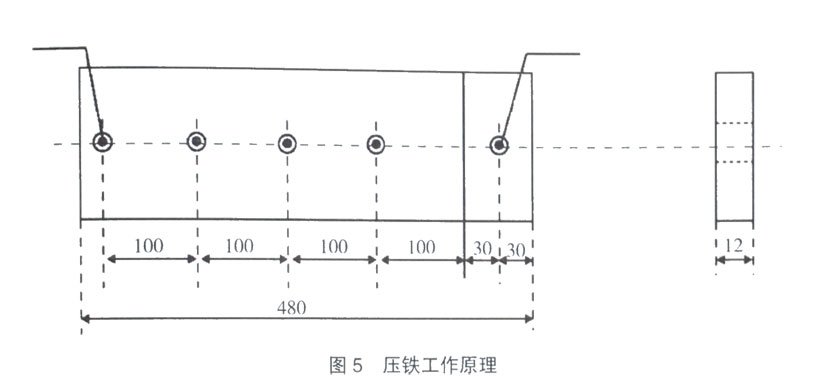
A problem is found in the process of operation, when the specification of the conveyor belt changes, it is necessary to replace the horn corresponding to the thickness and width of the specification, this process is more troublesome, and a large number of bolts need to be disassembled. In the process of practice, in order to cooperate with the production of products of different specifications, the author solves the above problems with self-made iron pressing, taking the production of products with a bandwidth of 1000mm as an example, and the design diagram of the working principle of iron pressing is shown in Figure 5.

Point A in Figure 5 and Point A in Figure 4 are bolted with M12 to form a rotatable pressing iron. The B end hole of this pressing iron is bolted with the horn L close to the belt body and the slider B below the belt body, so that all the horns in the middle position can be compressed, so that they can not move freely, and the horns in the middle position do not need to be fixed with bolts each. When it is time to replace the horn, simply disassemble the bolt close to the horn position to turn the press to another position. Of course, conveyor belt bodies with different widths require different lengths of pressed iron. This equipment requires 4 sets of pressers, each with a length of 480mm. 380mm、280mm、180mm。